
Issue 30–April, 1989
Dateline: New York—You think you've got pressure problems, wait till you hear what Kevin Pustay of New York Telephone was up against. Kevin was assigned to work pressure on twenty-five offices. His task was to increase the underground pressure to 5.0 PSI, the standard for New York Telephone. Unfortunately, during Kevin's eighteen years in the telephone company he never had the opportunity to work pressure. In addition, his crew had no experience, his pressure records were inaccurate, and the offices were in various stages of chaos. A formidable task to say the least. The only thing in Kevin's favor was the fact that he had attended one of System Studies' "Theory and Practice" classes, and he was able to take the skills he learned there and apply them to his situation.
When Kevin began leak locating in the Floral Park wire center, he decided that "hitting the streets" and finding what was out there was the only way to start. After 200 labor hours of repairing cable leaks on one route in this wire center, there was no significant increase in cable pressure. So, with nothing behind him except high labor costs, Kevin decided that research and analysis might be a better use of his time. (Kevin didn't know this then, but a successful and proven formula for leak locating is: Analyzation - 60%, Leak Locating - 25%, and Leak Repair - 15%.)
Finding the Source of the Pressure Problem
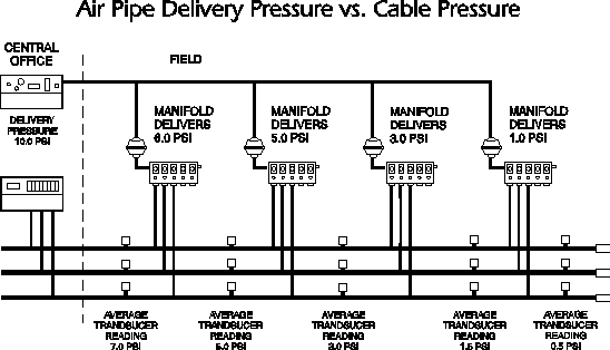
As with the majority of New York Telephone's cable pressure systems, Floral Park was designed using an air pipe concept. This concept is derived from placing an air pipe in each run adjacent to the cables. The cables are fed pressurized air through air pipe manifolds at approximately one mile intervals. The midpoint cable pressure between the manifolds (sources of air) are monitored by pressure transducers which are wired to the CPMS (Cable Pressure Monitoring System).
By analyzing the CPMS printout, Kevin found that the pressure readings for the transducers looked similar to those shown in the figure below. The pressure transducers in the first pneumatic section indicated an average pressure of 7.0 PSI. However, the transducers in each of the subsequent sections averaged less pressure, and the last pneumatic section had a cable pressure as low as 0.5 PSI.

In this situation, a technician would typically be dispatched to the end of the route to locate leaks and increase cable pressure. Unfortunately, the only thing that would be increased is labor hours and frustration. By chasing the lowest pressure, the technician may be leak locating in exactly the wrong location. Kevin knew that the difference in cable pressure was not attributed to leaks, but to the different delivery pressure in each of the pneumatic sections. He reasoned that if air were supplied to a pneumatic section at only 1.0 PSI, there'd be no way you could find a cable pressure higher than 1.0 PSI, unless there was another air source out there. Therefore, a delivery pressure of only 1.0 PSI will allow the highest cable pressure to be 1.0 psi.
So, Kevin narrowed his investigation to the air pipe. More specifically, to air pipe delivery pressure. From experience, Kevin has learned that there are two primary causes of low delivery pressure: low regulated pressure at the pipe alarm panel, and high air usage or consumption. After a visit to the central office, Kevin verified that the delivery pressure was 10.0 psi and concluded that the cause for the low delivery pressure was high air usage.
Using the Right Tool to Solve the Problem
Because measuring air flow was the key to solving the pressure problems of the Floral Park wire center, Kevin needed accurate flow measurements. The common tools used in the field are the flow transducer and portable flow rater. Kevin felt that neither tool could be relied on to give him the accuracy in measuring he needed. There are just too many variables when monitoring air pipe consumption: a flow transducer may be out of calibration; there may be a leak in the air pipe; or a manifold may be unmonitored. With the portable flow rater, air flows to the individual cables are rerouted through the flow rater via pressure testing valves and tubing. By shutting off a valve on the manifold, the air passes through the flow rater to the cable. Reading problems occur because the air must go through the two pressure valves. These valves significantly restrict the flow of air, causing an inaccurate flow reading.
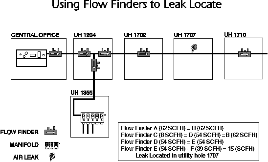
To eliminate this problem, Kevin chose to use System Studies Incorporated's Flow Finder and Flow Gauge. Flow Finders do not require the rerouting of air flow. They actually become a part of the system, therefore, their measurements are accurate. Kevin installed Flow Finders at the pipe alarm and meter panels, air pipe T's, and air pipe manifold locations. Because they are available in four flow ranges (0-9.5 SCFH, 0-19.0 SCFH, 0-47.5 SCFH, and 0-95.0 SCFH), he chose Flow Finders with the correct ranges and installed them at the appropriate locations. In conjunction with the Flow Finders, Kevin used the Flow Gauge (also developed by System Studies) to manually measure the air flow. The Flow Gauge measures the pressure differential over a calibrated orifice and converts it into an accurate flow rate.
As seen in the figure below, Flow Finders allow Kevin to verify all air usage and determine the location of the leak. By reading the flow rate of each individual Flow Finder, Kevin was able to identify the utility hole which housed the leak. Kevin continued this process along the pipe route until the flow rates added up.

The Pressure Problem Is Solved
Of the 60 utility holes on Pipe Route "B" in the Floral Park wire center, 17 Flow Finders, were installed at ten locations. Eighteen hours were required for installation of the Flow Finders, and an additional 16 hours were needed for reading and analyzing them. The air flow information provided by the Flow Finders helped Kevin and his crew perform the following:
Once the major leaks were identified, it required 48 hours to repair them. As a result, end point pipe pressures increased from 2.5 PSI to 6.0 PSI, and 75% of the pressure transducers that were in alarm were cleared.
Kevin's total investment—including the cost of the Flow Finders, Flow Gauge, and labor hours—resulted in more than a 50% savings of the initial maintenance cost invested in the wire center. And remember the initial cost resulted in no significant increase in cable pressure.
Two major conclusions can be drawn from Kevin's experience. First, increasing air pipe delivery pressure is an effective and efficient way to improve cable pressure, and second, Flow Finders are extremely accurate in chasing the air flow that causes low delivery pressure. Obviously, the information technicians receive from using Flow Finders significantly improves labor efficiency.
We're excited about Kevin's findings. As the "first kid on the block" to install and use the Flow Finders and Flow Gauges, Kevin saved New York Telephone a great deal of time and money. And for a guy who didn't initially know much about pressure, Kevin can now be considered a real expert in the field.
For more information regarding the Flow Finder and Flow Gauge, call 800-247-8255 outside California. Within California, call 831-475-5777.
© 1996-2018 System Studies Inc. All rights reserved.
(800) 247-8255 | (831) 475-5777