
by Bob Erickson, Bell Canada
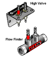
A Flow Finder is a mechanical device that is installed in an air pipe, allowing the technician to determine the flow rate of a pipe at the reading point. A High Valve Assembly extends the flow measurement point of the Flow Finder up to the maintenance collar where a technician can read the flow on a pipe without having to pump the maintenance hole. Flow readings taken at two adjacent Flow Finder locations (in the same pipe) will indicate whether or not there is a leak (or unrecorded air source) in the pipe section.
 I first heard of Flow Finders after seeing a product demo by one of the representatives from CG Industries Limited, the distributor of System Studies' pressurization products in Canada. I liked what I saw, particularly the ability of the Flow Finders to quickly and accurately track air consumption in an air pipe. In the Hamilton Main switch we have several long, high flowing pipe runs feeding 1800 and 2400 pair cables, some dating back to the 1920s and before. I felt that this office was a great place to try out the Flow Finder concept.
The cost of the equipment needed to flow the Hamilton Main switch came to a total of $CN6204.31 (Canadian). A total of sixty-four hours was required to install the Flow Finders on seven pipes.
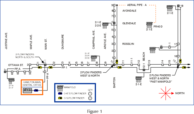
The goal for placing these Flow Finders was to find out—on each route—what pipe section or leg was consuming the most air. Once this information was determined, we would go back and fix the largest flows and move on to the next pipe. Our procedure was to place a 0-47.5 Standard Cubic Feet per Hour (SCFH) Flow Finder on each pipe in the office, and 0-19 SCFH Flow Finders with High Valve Assemblies in access holes at pipe legs or at specific locations along a pipe route.
After installing the Flow Finders, we took flow readings using the hand-held Flow Gauge and recorded them so that we could determine which pipe or pipe section was flowing the highest. I was surprised to find that it took only four hours to flow the Hamilton Main switch. The readings showed me which pipe legs or sections were leaking and where the majority of the air was going. The results of using Flow Finders were impressive. For example, leaks were repaired and pipe alarms cleared on Pipes E and C in one day.
An example of where Flow Finders were installed is shown on the schematic for Pipe A (see Figure 1).

Flow Finders were placed in the office and at maintenance holes 1-1, 10, and 15-1. The flow readings taken at these locations showed me that my only big flow (approximately 10 SCFH) was located somewhere between maintenance holes 10 and 15-1. It took only 15 minutes to narrow down the search area, without pumping one maintenance hole. Just as important, the readings told me that I did not have to waste my time on the other sections of the pipe. Eventually a cracked lead sleeve was repaired at MH 15-1, taking 10 SCFH off my pipe.
The Real Test
A few days after taking my initial flows on Pipe A, I arrived at work to find that the pipe had crashed. Twenty-two transducer alarms had come in overnight. However, in ten minutes using the Flow Finders, I found that the flow going down Barton Street had increased from 7 SCFH to 29 SCFH. Thirty minutes later I had located the leak without pumping a single maintenance hole. A hydro contact had blown a hole in a section of pipe when a road building machine had pulled our strand into hydro, causing an arc. Traditional methods of leak locating may have taken me all day to locate the problem.
I see many advantages in Flow Finders. Not only do they indicate if we have a pipe leak, they also tell the technician where the big flows are in the system. If your readings indicate a major flow down a pipe leg and your manifolds have small flows, there's definitely a pipe problem. Flow Finders will help you zero in on the pipe leak—something you could not do with traditional equipment and readings.
Considering that it took only four hours to flow one switch—a procedure that would have easily taken me two weeks using traditional methods—I am convinced that System Studies' Flow Finders are an excellent investment. At our loaded labor rate, these devices pay for themselves the first time you use them. That's why we also installed them on nine pipes in our Hamilton Hunter switch.
Based on the type of results we have had so far with Flow Finders, efforts are now being made to standardize them throughout Bell Canada. Hopefully, other areas will also soon be able to benefit from having Flow Finders installed on their pipe routes.
Bob Erickson is a Cable Repair Technician for Bell Canada. He has worked for the company for 11 years. Currently, his responsibilities include Air Pressure Maintenance, Cable Trouble and Fiber Optics.
Taking the Next Step in Flow Finder Installations
Bob Erickson's use of Flow Finders and High Valves in Bell Canada is a perfect example of how these simple devices can be used to quickly and easily identify leaking air pipe sections. In addition to placing the devices at selected locations in the air pipe and at pipe legs (tees), you can further extend your flow measurement capabilities by installing Flow Finders at air pipe manifold locations.
We recommend that you install one Flow Finder in the air pipe at each manifold hole (on the central office side of the air feed to manifold) and one in the tubing to the manifold (see Figure 2). If you are using Flow Finder Manifolds, which have built-in Flow Finders, you won't need to install a Flow Finder in the air feed tubing. By the way, you also only need one Flow Finder at the last manifold on the pipe.
The idea is to be able to measure both the incoming pipe flow rate (in order to account for all of the flow in the preceding pipe section) and the amount of flow that is being consumed by the manifold. That way, you can subtract the manifold flow from what is measured in the pipe to give you an accurate indication of what should be measured at the next Flow Finder toward the field.

Here's a scenario. Let's say the Flow Finder installed on Pipe A in a central office measures 60 SCFH. The next Flow Finder is installed in the air pipe four maintenance holes away. It also measures 60 SCFH. A Flow Finder installed in the tubing to the air pipe manifold at this location measures 30 SCFH Figure 2). You know you've got one or more high flowing cables here, but you also know that there are no leaks in the pipe section between the C.O. and MH 4.
In order to purify the next section of air pipe (between maintenance holes 4 and 8 in the illustration), you'll need to measure 30 SCFH (the original 60 SCFH, minus the 30 SCFH being used by the manifold). If 30 SCFH does not reach the Flow Finder installed in the pipe at MH 8, there's either a leak or an unrecorded air source in the pipe section.
Placing Flow Finders at each air pipe manifold location as described above will enable you to account for all of the air flow in your system and determine what percentage of the flow each manifold is consuming. They give you assurance that your pipe is in good shape, and they provide accurate information for leak locating in the cables.
© 1996-2018 System Studies Inc. All rights reserved.
(800) 247-8255 | (831) 475-5777