
Issue No. 28–January, 1989
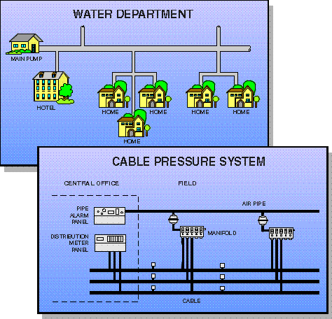
We have found that one of the best ways to explain the importance of measuring air flow in a cable pressurization system is by using the analogy of a water department. A water department monitors water usage and locates leaks using the same three basic principles that are at work in a cable pressurization system: pressure, flow, and the resistance of the water pipes and telephone cables. In this Gazette article we'll describe these three principles and discuss the relationship among them.
Pressure
Both water pressure and cable pressure are measured in Pounds per Square Inch (PSI). This measurement is the result of placing a physical force behind the water (such as pumping a large volume of water through a pipe) or physically compressing air molecules (such as the mechanical compression performed by central office air dryers). In either case a source of pressurized water or air can be provided.
Flow Rate
Water flow rates, used for determining customer consumption or the size of a pipe break, are measured in Cubic Feet per Minute. A pipe leak, for example, might use 500 Cubic Feet of water per Minute. Air flow rates in a cable pressure system are measured in Standard Cubic Feet per Hour (SCFH) or Standard Cubic Feet per Day (SCFD). A cable leak, for example, may use 5 Standard Cubic Feet per Hour, or an air pipe may consume 900 Standard Cubic Feet per Day. One Standard Cubic Foot per Hour is the same flow rate as 24 Standard Cubic Feet per Day.
Pipe Size
The size of a water main determines the potential of a water pipe to produce certain flow rates. Pipe size (diameter) is measured in inches. The larger the pipe, the less resistance there is to the flow of water. This results in a greater capacity for carrying water. The resistance in a cable, or the tendency to restrict air flow, is not entirely the result of cable size or diameter. This resistance, called pneumatic resistance, is determined by three things: 1) type of conductor insulation, 2) number of pairs, and 3) conductor gauge.
Pneumatic resistance is measured in units of resistance per 1,000 feet. The higher the pneumatic resistance, the smaller (tighter) the cable will be. This basic relationship between pressure, flow, and resistance can help to explain several basic concepts.
What's the Cause of Low Pressure?
If a water department is required to ration water during a drought, it has to determine a fair system of distribution. For example, if there are two apartment buildings, how much water should be allocated for each? Obviously, the fairest thing to do would be to base the amount of water given to each building on the number of people who live there. If one of the apartments has four times as many residents as the other, it should be allowed four times as much water. It would be unfair and impractical to allocate a fixed amount to each apartment.
Determining an amount of air usage in a cable pressure system is very similar to this water rationing analogy. Instead of counting the number of people served, we would count air usage per pressurized sheath mile of cable. The accepted usage for a cable pressure system is 30 SCFD or 1.25 SCFH per sheath mile of cable. Ten sheath miles of cable should use no more than 300 SCFD; 20 sheath miles should use no more than 600 SCFD. The standard or acceptable air consumption for a cable pressurization system is called Optimum Air Usage, or OAU. Using this optimum air flow concept, it's easy to see how the highest flowing route in a wire center could, theoretically, be in the best shape.
This analogy is useful in explaining the sizing of air dryers/compressors for a central office. Obviously, the size of dryer required depends upon the number of pressurized sheath miles of cable being fed. System Studies Incorporated recommends that when sizing a dryer, you take the total number of pressurized sheath miles in the office and multiply that figure by 100 SCFD (3 times standard plus some). Based on this calculation, you can select a dryer that will maintain the estimated output.
How Much Cable Can You Feed with an Air Pipe?
When an engineer for a water department installs a new water main, he or she sizes the pipe based upon the potential of customers in the area the pipe will feed. Knowing that an average household uses "x" amount of cubic feet of water, the engineer can size the pipe accordingly. Logically, the more customers there are, the bigger the diameter of the pipe must be.
When a cable pressure engineer is placing air pipe for a system, he or she faces a similar, but slightly different problem. While the number of pressurized sheath miles being fed varies, the engineer has only one pipe diameter size to use. It has been calculated that the standard 1/2" CA 3131 air pipe used throughout the telephone industry can feed up to 20 sheath miles of pressurized cable. Adequate delivery pressure may be hindered if more than 20 sheath miles of cable are being fed from one pipe. If the total sheath mileage exceeds this requirement, an additional air pipe (rather than a larger diameter) would need to be installed.
You can see from this example that engineering can and does have a major impact on maintaining minimum cable pressures.

What Are the Reasons for Good Flow and Bad Flow?
When you turn your shower on in the morning and all you get is a drip or two of water, you can assume (and correctly too!) that the pressure has dropped in your water line. It's an aggravating situation, one that's the result of three or four possible conditions:
This example emphasizes an important concept in cable pressurization. Just because a cable has low air pressure, it does not necessarily mean that there is a leak in that particular cable. Low cable pressure can be caused by a number of things.
First of all, the air pressure originating in the central office may be low. Standards dictate that minimum delivery pressure from the central office should be 10.0 PSI. A delivery pressure of 7.0 PSI, for example, just doesn't cut it. It's like having two strikes against you before you even step up to the plate.
Secondly, you might be feeding too many total sheath miles of cable with one air pipe. It's impossible to expect satisfactory water pressure in a large hotel when only a one inch water main is supplying water. The same is true in an air pressure system. It's impossible to expect cables to receive adequate delivery pressure (7.5 PSI minimum) if more than 20 sheath miles of cable are being fed from one air pipe. Unless you use another air source, you just can't expect to maintain 7.0 PSI in the underground if the air pipe feeding these cables is only delivering 5.0 PSI.
Third, an air pipe leak or major cable leak near an air source will reduce cable pressures throughout the cable route. These large, high consumption leaks lower delivery pressure. Until they are found, you can never expect to restore cable pressure in a route.
In a water system, a large leak or break in the main feeder pipe will cause low water pressure at a home, even if no water at that house is being used. A large leak will not only drop delivery pressure to your home, but also to your neighborhood.
Finally, a large leak in a cable (or excessive water usage at a house) will bring down local cable pressure. While this is only one of four possibilities, it is usually the one most often considered when leak locating in a cable pressurization system. This assumption can result in many wasted labor hours. Before you actually begin leak locating, it is absolutely critical for you to determine the reason for low cable pressure. It is not enough to merely identify that a low cable pressure condition exists. You have to examine the possible causes for the low cable pressure.
Using Flow Rates in Leak Locating
The use of flow rates in leak locating activities is a valuable tool for both the water department and cable maintenance personnel.
As discussed earlier, the water department measures water flow rates in Cubic Feet per Minute. A typical, or average residential usage rate would be between 0 and 2 Cubic Feet per Minute. If a water main were broken and the repair crew knew that water usage had increased 500 Cubic Feet per Minute, they'd be able to determine the general location of the leak. At least they would certainly know where not to look. Looking down a street that has a 2 inch water main would not only be ridiculous, it would be a total waste of time. It would be impossible for a leak in this area to flow 500 Cubic Feet per Minute because of the small diameter of the pipe. A leak that size would have to be in a main that is large enough to carry the high flow rate.
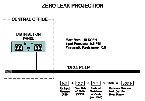
The same is true in a cable pressurization system. Knowing the amount of air a leak is consuming is critical in determining the location of the leak. The known flow rate, the input pressure, and the pneumatic resistance of the cable help define a general area where the leak could exist. The flow rate is measured in Standard Cubic Feet per Hour (SCFH), and the input pressure in Pounds per Square Inch (PSI). Using these measurements, a Zero Leak Projection, or ZLP can be calculated (see below). The ZLP will indicate the farthest point from where air is placed into the system that a leak could be and still use the amount of air measured.

The ZLP doesn't really tell you where the leak is, but it does tell you where it isn't. And it's our belief at System Studies that most leak locating (nearly 80%) takes place in areas where the leak cannot possibly be.
Prioritizing Leaks
Another similarity between the water department and the cable maintenance department is the process of deciding what leak or leaks to work on. In both systems, there are a number of general leaks. Some have a major impact on water and air pressure, and others are so small they are not economically worth fixing. The problem is deciding which ones should be fixed first and which ones can wait. It's a matter of establishing priorities.
In a water department, measuring pressure alone won't tell the whole story. Low pressure in an area may not necessarily be the result of a leak, but actually the improper sizing of the water main feeding the area. Fixing the leak in this main may help a few houses in the immediate area, but it will have virtually no impact on improving pressures in the rest of the system. The greatest improvement will be seen if the leak that is using the most water (highest flow rate) is fixed first.
This can also be applied to the air pressure system. When you look for a cable leak that has the largest impact on the system, it is best to use air consumption as a prioritizing tool.
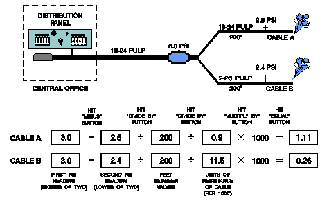
The figure below shows a main cable that feeds two laterals, both of which have leaks. The pressure measurements taken are shown. While Cable B has the lowest cable pressure (2.4 PSI), it is Cable A that is doing the most damage. Why? As determined by the two air flow calculations (see boxes at the bottom of diagram), the leak in Cable A is consuming nearly five times more air than the leak in Cable B. Therefore, the leak in Cable A is damaging the system five times more than the smaller leak in Cable B. If the leak in Cable A were fixed first, Cable B would rise to the same pressure as the main cable splice (3 PSI). This pressure is determined by the leak in Cable A.

Calculating the air flow rates of cables provides the information needed to determine which leak to fix first. For further information on how to calculate air flow rates, see Page 4-23 of the System Studies Theory and Practice Manual. Using this formula, you can direct your efforts toward fixing the most damaging leak--the one that is pulling delivery pressure down.
In a cable pressurization system, a primary objective is to improve cable pressures and maintain adequate protection. Hopefully, the analogies and formulas discussed in this article have shown that the best approach to achieving this goal is through the analysis and use of air flow.
© 1996-2018 System Studies Inc. All rights reserved.
(800) 247-8255 | (831) 475-5777