Flow Finder Uses
About Air Flow Restriction
Flow Finder Engineering Symbols
Identifying Bad Flow TDs
Checking FTD Accuracy
Choosing Flow Finder Ranges
Flow Finders/Pipe Purification
Flow Finders & High Valves
Flow Finder vs. Portable Flow Rater
Miscellaneous Topics
Flow Gauge Conversions
Using Flow Finders on Route that Does Not Have Flow Transducers
Concerning Pressure Drop

Article #12: Using Flow Finders on a Route
That Does Not Have Flow Transducers
October 23, 2006In our previous Tip of the Week articles we've discussed using Flow Finders™ in conjunction with flow transducers on a route. Although this is the most common application, we'd like to examine the use of Flow Finders on a route that does not have flow transducers.
If you don't already have flow transducers installed in your system, there are a number of reasons why Flow Finders may be the most logical alternative: 1) Flow Finders do not require engineering; 2) they are quick to install; 3) they are less expensive than flow transducers; 4) Optimum Air Usage (OAU) calculations can be determined for Flow Finders; 5) and, unlike flow transducers, Flow Finders can be used for identifying leaks in the air pipe. In fact, this is one of their primary functions. Finally, they provide more accurate measurements for chasing air flow.
Installing Flow Finders to use as the only flow measuring devices on a route involves purifying air pipes. Using Flow Finders to purify a pipe identifies the major problems along the route, the ones that reduce delivery pressure. When purifying air pipe, Flow Finders should be installed at the following locations: Pipe Alarm Panels, air pipe (in line), air pipe junctions and air pipe manifolds.
Flow Finders measure air flow and help to localize an area of search when leak locating. For example, let's say that a technician is dispatched to leak locate on a route that has recently been purified with Flow Finders installed at the locations listed above. Figures 1, 2 and 3 show examples of how the technician can take flow readings at the central office and in Manhole B to narrow the area of search.
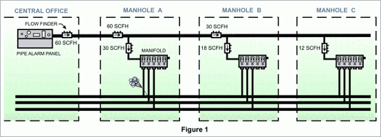
Figure 1 shows readings of 30 SCFH on the pipe and 18 SCFH at the manifold in Manhole B. A reading of 60 SCFH was measured at the Flow Finder in the central office. Since 30 SCFH is coming into the manhole and 60 SCFH is leaving the central office, a flow of 60 SCFH can be estimated for Manhole A. That's assuming, of course, that there are no new pipe leaks. Visiting Manhole A reveals a reading of 60 SCFH at the Flow Finder on the pipe. The Flow Finder located on the manifold records a reading of 30 SCFH. This high flow indicates a major leak on the cable. Therefore, the area of search is narrowed to the cables in Manhole A.
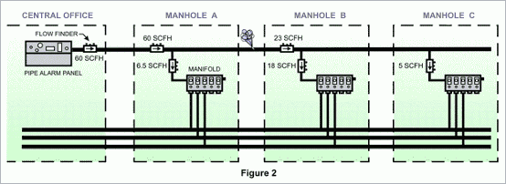
 The Flow Finder readings in Figure 2 indicate that there is 23 SCFH on the pipe and 18 SCFH in Manhole B. Another Flow Finder reading in the central office reveals that 60 SCFH is heading toward the field. A visit to Manhole A for a quick reading at the Flow Finder on the air pipe shows that there is still 60 SCFH flowing through the pipe. Another reading of 6.5 SCFH is taken at the Flow Finder located on the manifold. These two readings indicate that 53.5 SCFH should be flowing into Manhole B. However, the 23 SCFH reading obtained at Manhole B narrows the area of search between Manholes A and B. In this example, there is a section leak consuming approximately 30 SCFH of air.

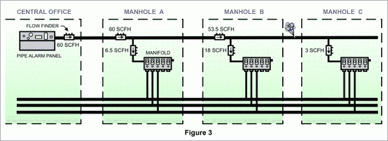
Figure 3 displays a reading of 53.5 SCFH on the pipe and 18 SCFH in Manhole B. With the reading of 60 SCFH at the central office, a loss of 6.5 SCFH can be estimated between the central office and Manholes A and B. Compared to the total flow, this low amount of flow is insignificant. However, the flow going toward the field is important. By subtracting the readings obtained at Manhole B (53.5 SCFH minus 18 SCFH), it is calculated that 35.5 SCFH should be flowing to Manhole C. Visiting Manhole C reveals a reading of only 3 SCFH at the Flow Finder at the manifold. Therefore, the area of search is narrowed between Manhole B and Manhole C.

These examples demonstrate how practical Flow Finders are in narrowing down an area of search. They are not a substitute for flow transducers, and we're not suggesting that you replace your flow transducers with them. But, if you have a route without any flow measuring devices installed, Flow Finders are an alternative worth consideration.
If you don't already have flow transducers installed in your system, there are a number of reasons why Flow Finders may be the most logical alternative: 1) Flow Finders do not require engineering; 2) they are quick to install; 3) they are less expensive than flow transducers; 4) Optimum Air Usage (OAU) calculations can be determined for Flow Finders; 5) and, unlike flow transducers, Flow Finders can be used for identifying leaks in the air pipe. In fact, this is one of their primary functions. Finally, they provide more accurate measurements for chasing air flow.
Installing Flow Finders to use as the only flow measuring devices on a route involves purifying air pipes. Using Flow Finders to purify a pipe identifies the major problems along the route, the ones that reduce delivery pressure. When purifying air pipe, Flow Finders should be installed at the following locations: Pipe Alarm Panels, air pipe (in line), air pipe junctions and air pipe manifolds.
Flow Finders measure air flow and help to localize an area of search when leak locating. For example, let's say that a technician is dispatched to leak locate on a route that has recently been purified with Flow Finders installed at the locations listed above. Figures 1, 2 and 3 show examples of how the technician can take flow readings at the central office and in Manhole B to narrow the area of search.
Figure 1 shows readings of 30 SCFH on the pipe and 18 SCFH at the manifold in Manhole B. A reading of 60 SCFH was measured at the Flow Finder in the central office. Since 30 SCFH is coming into the manhole and 60 SCFH is leaving the central office, a flow of 60 SCFH can be estimated for Manhole A. That's assuming, of course, that there are no new pipe leaks. Visiting Manhole A reveals a reading of 60 SCFH at the Flow Finder on the pipe. The Flow Finder located on the manifold records a reading of 30 SCFH. This high flow indicates a major leak on the cable. Therefore, the area of search is narrowed to the cables in Manhole A.


Figure 3 displays a reading of 53.5 SCFH on the pipe and 18 SCFH in Manhole B. With the reading of 60 SCFH at the central office, a loss of 6.5 SCFH can be estimated between the central office and Manholes A and B. Compared to the total flow, this low amount of flow is insignificant. However, the flow going toward the field is important. By subtracting the readings obtained at Manhole B (53.5 SCFH minus 18 SCFH), it is calculated that 35.5 SCFH should be flowing to Manhole C. Visiting Manhole C reveals a reading of only 3 SCFH at the Flow Finder at the manifold. Therefore, the area of search is narrowed between Manhole B and Manhole C.

These examples demonstrate how practical Flow Finders are in narrowing down an area of search. They are not a substitute for flow transducers, and we're not suggesting that you replace your flow transducers with them. But, if you have a route without any flow measuring devices installed, Flow Finders are an alternative worth consideration.