TD Housing Splice Assembly
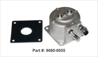
 The TD Housing Splice Assembly (Part No. 9080-0055) makes it easy to utilize retired device pairs located in an existing 5- or 10-bank transducer housing when installing a System Studies Manifold Monitoring Assembly. The housing mounts directly onto the transducer housing and accepts the 3/8" conductor pair tubing attached to the High Resolution Transducer's wire cover assembly. In addition to the 3/8" tubing fitting, the splice assembly is equipped with a tank valve that can be used for flash testing after device wiring and installation procedures have been completed. The mounting gasket supplied with the assembly includes a center cutout for access to the monitoring pair. It also serves to ensure a leak-free connection to the TD housing.
The splice assembly was designed for situations where a 6,000 foot air pipe manifold spacing design is being converted to a 3,000 foot design. This design conversion requires the removal of existing midpoint pressure transducers and the installation of a Manifold Monitoring Assembly at the midpoint location. Consequently, there is an abundance of available, pre-wired transducer pairs in the housing.
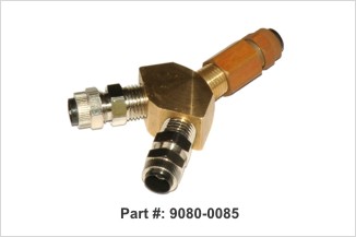
In a typical installation the monitored manifold's flow tranducer pair (blue, blue/white) would be connected to the working pair in transducer housing slot #1. If the Manifold Monitoring Assembly is equipped with a High Resolution Dual (pressure/flow) Transducer, a second TD Housing Splice Assembly will be required in the slot #2 position. The pressure device pair (orange, orange/white) would be wired to the working pair in slot #2. For the dual transducer installation, System Studies provides the Pair Splitter "Y" Connector (Part No. 9080-0085) shown below. The splitter makes it possible to separate the two transducer pairs, insert them into two lengths of 3/8" tubing and connect them to the splice assemblies at the housing.
 The Pair Splitter "Y" Connector is supplied with two pulling wires that make it possible to route the transducer pairs through the fitting without having to disasemble it.
For more installation information on this equipment, check out our data sheet.
 The TD Housing Splice Assembly (Part No. 9080-0055) makes it easy to utilize retired device pairs located in an existing 5- or 10-bank transducer housing when installing a System Studies Manifold Monitoring Assembly. The housing mounts directly onto the transducer housing and accepts the 3/8" conductor pair tubing attached to the High Resolution Transducer's wire cover assembly. In addition to the 3/8" tubing fitting, the splice assembly is equipped with a tank valve that can be used for flash testing after device wiring and installation procedures have been completed. The mounting gasket supplied with the assembly includes a center cutout for access to the monitoring pair. It also serves to ensure a leak-free connection to the TD housing.
The splice assembly was designed for situations where a 6,000 foot air pipe manifold spacing design is being converted to a 3,000 foot design. This design conversion requires the removal of existing midpoint pressure transducers and the installation of a Manifold Monitoring Assembly at the midpoint location. Consequently, there is an abundance of available, pre-wired transducer pairs in the housing.
In a typical installation the monitored manifold's flow tranducer pair (blue, blue/white) would be connected to the working pair in transducer housing slot #1. If the Manifold Monitoring Assembly is equipped with a High Resolution Dual (pressure/flow) Transducer, a second TD Housing Splice Assembly will be required in the slot #2 position. The pressure device pair (orange, orange/white) would be wired to the working pair in slot #2. For the dual transducer installation, System Studies provides the Pair Splitter "Y" Connector (Part No. 9080-0085) shown below. The splitter makes it possible to separate the two transducer pairs, insert them into two lengths of 3/8" tubing and connect them to the splice assemblies at the housing.
 The Pair Splitter "Y" Connector is supplied with two pulling wires that make it possible to route the transducer pairs through the fitting without having to disasemble it.
For more installation information on this equipment, check out our data sheet.